PCB Design Class - February '23
During MIT’s 2023 independent activities period (IAP) I took a 6 unit class on The Art and Science of PCB Design. I had already had practice making simple circuit layouts to be milled, but this class was very informative about all aspects about PCB design.
Inspiration and Purpose
Initial Inspiration
At first I wanted to create a device that would allow “simple communication”. The idea being that if you and a group wanted to have a simple way to communicate predefined commands such as “come back” or the state of objects.
The simplest example for this is when I teach single rope technique. Having a small box with an LED to display if the rope is in use or not at the bottom of a tall stairwell that synchronizes with a similar box at top would make communicating whether a rope is safe to use or if it’s occupied much easier as the stairwell echos too much to speak clearly. Using battery power, an ESP32 microcontroller, and LORA modules these communicators would offer a niche middle ground between wanting some more advanced ways to communicate without needing handheld radio or walkie-talkie.
Ultimately I did not decide to pursue this inspiration for this class as I was more excited to work on a different idea that I felt was more necessary and useful to have. I plan on creating this eventually with support of the MIT Radio Society to explore LORA propagation on campus.
Final Idea
The idea I pursued is based on the circuit I heavily worked with during my senior product design capstone course (expect a blog entry soon). For our project, we wanted to make shop disc sanders safer. This involved using a band brake to stop the sanding disc faster than the blink of an eye.
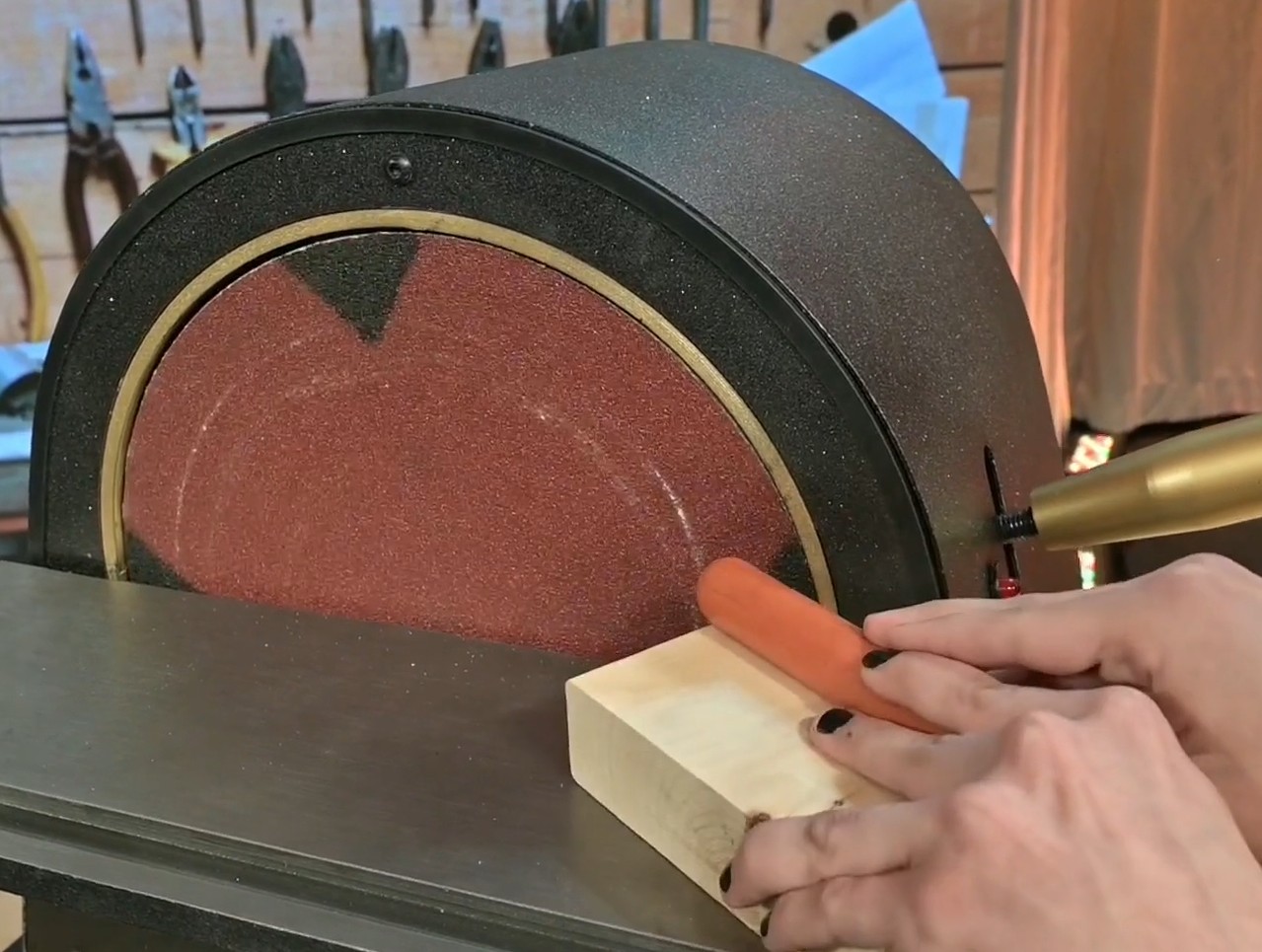
To do this, we used capacitive sensing to detect whenever something conductive (such as human flesh) was approaching too quickly or made contact with the front disc.
Solving the capacitive sensing problem proved to be very difficult. For the longest time we were were trying to use a methodology that involved measuring the time constant of our virtual capacitor (the human body) through a resistor. This proved to be slow and very unreliable. Most of the time we would read the initial discharge of static electricity instead of actual capacitance. Measuring the time constant approach was very simple and works well when there is direct contact with metal or anything conductive, but in our case we had a non-conductive layer of sandpaper so that was not an option for us.
Near the end of the project we looked into oscillation circuits that had a capacitance sensing component. This is the same style of sensing that a theremin musical instrument implements.
With help from our friend Oliver, we tested a circuit he found on https://gasstationwithoutpumps.wordpress.com/2012/07/12/capacitive-sensing-with-op-amps/. In an hour we constructed the circuit and saw we could accurately and precisely detect our hands from multiple inches away by counting the frequency. This type of detection also helped as the amount of data points we had were much more as the circuit oscillates around 60Khz. With this we have the two major advantages that we can implement low pass filters without compromising significant detection speed and sample rate is fixed (counts/time) vs. time it takes to charge.
Before finding this oscillation based solution we tried multiple existing/premade capacitive touch solutions such as the MPR121 or CAP1188 chip which have online breakouts with I2C or SPI connections. But they did not offer in depth data or even sensed well as they likely use the first method. This PCB aims to be a concise way to add very sensitive capacitive sensing to an existing project by providing an I2C interface to 3 channels using an ATtiny85.

Schematic
The schematic uses a 4 opamp chip such as the MCP6004 to set Vbias and create for capacitive sensing outputs which can be externally connected. After passing through a Schmidt Trigger IC the signal goes to pin change interrupt pins on the ATtiny85 to preform frequency counting and filtering. This ATtiny85 also uses the SDA and SCL pins to expose itself as a I2C peripheral device. This allows any project to have this advanced capacitive sensing without being bogged down doing frequency counting and the filtering of its own. Something also that’s neat is that the ATtiny85 can be reprogrammed to output different information on the I2C bus depending on what the user programmed.

Layout
The goal for the layout of this board is to make it versatile and easy to use for general projects. This is why all components are through hole. Some components even have sockets. For instance, the slew rate of the Op Amp IC is the limiting factor for the precision and speed of the sensing. For a project, we used a $20 opamp IC that was extremely fast as we needed to minimize sensing speed by collecting as many data points as possible. For general use the MCP6004 would be much more affordable and perfectly fine so either one can be placed in the socket as they share a pin layout. The same can be said for the resistors as changing their values can also have an effect on how well the capacitance works.
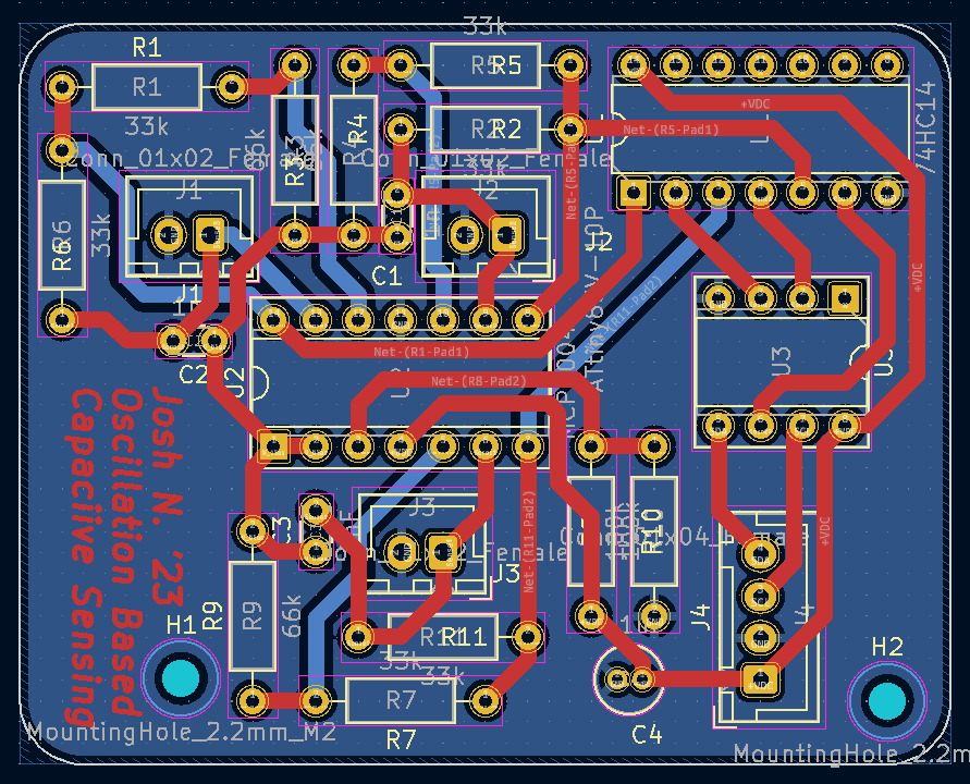
It’s important to note that traces were deliberately made 1mm to make this board possible to make on a desktop mill (which is also why instead of writing my name on the silkscreen layer I wrote it on the copper layer lol). I intend to test circuit by manually milling it out.
More things I enjoy about this layout that most connections can be made on one side. Which leaves one side almost completely free for a ground plane.
The 2-pin JST connections are meant to carry a signal and a ground connection in case shielded wire or coax is desired and the 4-pin JST connector carries power, ground, and the I2C lines from the controller board.

Future Ideas
This type of board could be interesting to commercialize which is a thought I’ve had in the back of my mind. Future design ideas involve making a compact version meant to be manufactured professionally and used in smaller scenarios or designing a version that does not include the ATTiny85 and is made even smaller to just be soldered to pins on an existing microcontroller. Also, one of four opamps is solely used as a buffer to half the incoming voltage. This is done such that the board can work with 3.3V or 5V. If I could find a component that could replicate this behavior I could free this opamp for a 4th capacitive sensing channel.
Conclusions
It was a lot of fun researching components and creating a layout while being thoughtful about how I would realistically use and make this PCB. I look forward to using this PCB to add hidden touch sensors for a hidden door perhaps. Although the class recommended Altium, I was happy to practice my skills in KiCad and support open source software.